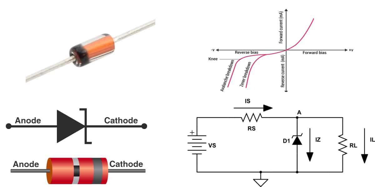
Electronic power supply circuits require a consistent voltage to operate safely and efficiently. However, fluctuations in input voltage and changes in electrical load can cause unwanted variations in output voltage. These changes may affect sensitive components, reduce circuit performance, or even cause permanent damage. Voltage regulation is therefore an essential part of reliable electronic design. One commonly used component for this purpose is the Zener diode, which helps maintain a relatively stable voltage across a circuit even when the input supply or load conditions change.
A Zener diode is a specially designed semiconductor device that operates in the reverse-breakdown region to regulate voltage. Unlike an ordinary diode, which is generally used for forward conduction or reverse blocking, it can maintain an almost constant voltage when connected appropriately in a circuit. Understanding how a Zener Diode works helps engineers, technicians, and electronics enthusiasts select suitable components for voltage regulation, reference circuits, and basic power supply protection.
What Is a Zener Diode?
A Zener diode is a semiconductor diode designed to conduct current in the reverse direction once the applied voltage reaches a specified value called the Zener voltage. Below this breakdown threshold, only a small leakage current normally flows. When the reverse voltage reaches the rated breakdown level, the diode begins conducting significantly while keeping the voltage across it relatively stable.
Zener diodes are manufactured with carefully controlled semiconductor doping to achieve a predictable breakdown voltage. They are available in different voltage ratings and power capacities, allowing designers to choose a component that matches the requirements of a particular electronic application.
Key Characteristics of a Zener Diode
Several characteristics make Zener diodes useful in voltage regulation circuits:
- Specified breakdown voltage: Each device has a rated voltage at which reverse conduction becomes significant.
- Voltage regulation: It maintains a relatively stable voltage across its terminals within its operating range.
- Reverse-bias operation: Its primary voltage-regulation function occurs when it is connected in reverse bias.
- Current-handling capability: Different models support different operating currents.
- Power rating: The maximum power dissipation determines how much electrical energy the device can safely handle.
How a Zener Diode Maintains Stable Voltage
The voltage-regulation process depends on the diode’s ability to operate in its reverse-breakdown region. When the input voltage reaches the required level, the diode conducts enough current to keep the voltage across itself close to its specified Zener voltage.
A typical Zener voltage regulator includes a DC input source, a series resistor, a Zener diode, and a load connected in parallel with the diode. The resistor limits current, while the Zener diode regulates the voltage supplied to the load.
Step-by-Step Working Principle
The operation of a basic Zener voltage regulator can be explained through the following stages:
- Input voltage is applied: A DC supply provides electrical energy to the circuit through a series resistor.
- Reverse bias is established: The Zener diode is connected with its cathode toward the positive supply, allowing it to operate in reverse bias.
- Breakdown voltage is reached: When the reverse voltage reaches the diode’s rated Zener voltage, it begins conducting.
- Output voltage is regulated: The voltage across the diode and parallel load remains approximately equal to the Zener voltage.
- Current adjusts automatically: If the input voltage or load current changes, the Zener current changes within its permitted operating range to help maintain the output voltage.
This arrangement provides a simple and economical way to produce a stable reference or regulated voltage for low-power electronic circuits.
Role of the Series Resistor in Voltage Regulation
The series resistor is an essential part of a Zener diode regulator. Without it, excessive current could flow through the diode after breakdown, potentially causing overheating and permanent damage.
The resistor performs two main functions:
- Limits the total current supplied to the Zener diode and load.
- Drops the excess input voltage while allowing the diode to maintain the required output voltage.
The resistor value can be estimated using Ohm’s law:
[
R_S=\frac{V_{IN}-V_Z}{I_Z+I_L}
]
Where:
- (R_S) = Series resistance
- (V_{IN}) = Input voltage
- (V_Z) = Zener voltage
- (I_Z) = Zener current
- (I_L) = Load current
The resistor must be selected carefully so that the Zener diode receives enough current to remain in its regulation region without exceeding its maximum current or power rating.
What Happens When Input Voltage Changes?
One of the main advantages of a Zener regulator is its ability to compensate for moderate input voltage variations.
When the input voltage increases, the additional current is largely absorbed by the Zener diode, provided the series resistor and device ratings are correctly selected. This helps prevent the output voltage from rising significantly.
When the input voltage decreases, the Zener current reduces. As long as the diode receives sufficient current to remain in its breakdown region, the output voltage stays close to the specified value.
However, if the input voltage falls too low, the Zener current may drop below the minimum required for regulation. In that situation, the output voltage can also decrease.
How a Zener Diode Responds to Load Changes
Load variations can also affect the current distribution in a voltage regulator circuit. When the load requires more current, a larger portion of the available current flows through the load, leaving less current for the Zener diode.
When the load current decreases, more current becomes available to flow through the diode. This allows the circuit to maintain its output voltage under changing load conditions, provided the diode remains within its specified operating limits.
For reliable performance, designers must consider both the minimum Zener current required for regulation and the maximum current the device can safely handle.
Important Factors When Selecting a Zener Diode
Choosing the correct Zener diode is essential for achieving stable voltage regulation and protecting electronic circuits. Several technical factors should be considered before selecting a component.
1. Zener Voltage Rating
The Zener voltage should match the required output or reference voltage. A diode with an unsuitable voltage rating may provide an output that does not meet the circuit’s operating requirements.
2. Power Dissipation
The diode must safely handle the power generated during reverse-breakdown operation. Its approximate power dissipation is calculated as:
[
P_Z=V_Z\times I_Z
]
The selected device should have an adequate power rating, with appropriate design margin and consideration of operating temperature.
3. Current Requirements
The diode must operate within its specified minimum and maximum current limits. Designers should calculate the current available under both light-load and heavy-load conditions.
4. Voltage Tolerance
Zener diodes are manufactured with different voltage tolerances. A tighter tolerance may be necessary in circuits where output accuracy is particularly important.
5. Temperature Stability
Zener voltage can change with temperature. The temperature coefficient depends on the breakdown voltage and the diode’s internal operating mechanism. This factor matters in equipment exposed to changing environmental conditions.
Common Applications of Zener Diodes in Power Supply Circuits
Zener diodes are used in various electronic applications where a relatively stable voltage or basic voltage protection is required.
Voltage regulation: They provide simple shunt regulation in low-power DC supply circuits.
Voltage reference circuits: Their predictable breakdown voltage makes them useful as reference sources for measurement and control systems.
Overvoltage protection: They can help limit voltage increases and protect sensitive components when used in appropriately designed protection circuits.
Signal clipping: Zener diodes can restrict signal voltage levels in waveform-shaping applications.
Transistor biasing: They provide a reference voltage that can help establish stable operating conditions in transistor circuits.
Microcontroller and sensor circuits: Suitable Zener-based circuits can provide basic voltage clamping or reference functions, although precision and current requirements must be evaluated carefully.
Advantages and Limitations of Zener Voltage Regulators
Zener diode regulators are popular because of their straightforward design and relatively low component cost. However, they are not suitable for every power supply application.
Advantages
- Simple circuit design with few components.
- Low implementation cost.
- Useful for basic voltage regulation and reference applications.
- Fast response to moderate voltage changes.
- Available in a wide range of voltage and power ratings.
Limitations
- Lower efficiency than many switching regulator designs.
- Limited current-handling capability in basic configurations.
- Output voltage changes with temperature and operating current.
- Requires a properly calculated series resistor.
- Not ideal for applications requiring high output current or very precise regulation.
For demanding power supply systems, designers may choose linear regulator ICs or switching regulators instead of relying on a basic Zener circuit.
Practical Design Considerations for Reliable Performance
A successful Zener voltage regulator requires more than selecting a diode with the correct voltage rating. The complete circuit must be evaluated under different operating conditions.
First, calculate the minimum available input voltage and maximum expected load current. These conditions help determine whether sufficient current will remain available for the Zener diode to stay in breakdown. Next, calculate the maximum Zener current under the highest input voltage and lightest load condition. This ensures that the diode does not exceed its power rating.
Thermal performance should also be considered. A diode operating close to its maximum power dissipation may require additional design margin or improved heat management. Finally, verify the circuit using practical measurements to confirm that the output remains within the required voltage range.
Conclusion
A Zener diode maintains stable voltage in electronic power supply circuits by operating in its reverse-breakdown region. When connected with a suitable series resistor and load, it adjusts its current to compensate for moderate changes in input voltage and load demand. This makes it a useful component for basic voltage regulation, reference generation, and overvoltage protection.
Although Zener regulators have limitations in efficiency, accuracy, and current capacity, they remain valuable in many low-power electronic designs. By understanding their working principle, selecting suitable voltage and power ratings, and calculating current requirements correctly, engineers can build reliable circuits that provide consistent voltage for electronic components.